- Cart
- |
- Personal Center
- |
info@idealphotonics.com


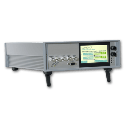
TDLAS Laser Gas Analysis Comprehensive Controller 1.0A 3.3V
This product is a control module designed for Tunable Diode Laser Absorption Spectroscopy (TDLAS). Its main functions include: generating a digital laser driver with superimposed sine and triangular waves, adjustable gain, adjustable gain amplifier, 1f/2f digital lock-in amplifier, and an analog output temperature control unit. Operating parameters and waveforms can be controlled and read from a computer.
Product features:Compact structure 、Easy operation
Part Number:--
Application area:Gas analysis 、Laser driver
Add to Cart Consult Favorite
Parameters
Technical Specifications | Parameters |
Power Supply | 100 ~ 240 VAC |
Laser Packaging | 14-pin butterfly package |
Optical Output Direction | Front panel, fiber optic output |
TEC Drive Current | 1.0A max |
TEC Drive Voltage | 3.3V max |
Temperature Control Range | -10 ~ 50℃ |
Laser Driver Power | < 2.7V @ 50mA, < 2.2V@100mA |
Scanning Current | 0 ~ 116 mA |
Sine Wave Current | 20kHz ~ 50kHz, 0 ~ 30mA p-p |
Amplifier Input | max 5 V p-p, AC coupling |
Demodulation Method | digital, 1famplitude, 2fwith phase |
Variable Gain Amplifier | x1, x2, x4, x8 |
Analog Output | 0 ~ 2.5V |
Communication Method | USB 1.1, PC software or console |
Dimensions | 340(L) x 240(W) x 100(H) mm |
Product Function Block Diagram

Laser Installation and Selection:
Remove the six M3 screws on the side of the instrument and open the top cover. Secure the butterfly laser to the corresponding holes on the mounting plate using four M2.5x6 screws. Connect the wiring according to the laser pin sequence. Attach the fiber port to the panel output, and use cable clips to manage the fiber routing if necessary. We recommend that customers use lasers provided by our company to avoid rendering the control system unusable due to improper installation. We strongly recommend NTT or Sumitomo DFB lasers, which offer high power, stable performance, and no mode-hopping issues. Note that the mounting plate can be rotated or flipped, and the M3 holes can be used to install cable clips.
Usage:
Connect the controller to mains power and use a USB cable to connect it to a computer. Press the power button on the front panel to turn on the controller. For Windows 7 and above, the system will prompt automatic online installation of the USB driver. For other systems or when there is no internet connection, please download the appropriate driver from http://www.ftdichip.com/Drivers/VCP. Once the driver is installed, a virtual serial device will appear in the "Device Manager."
Open the dedicated software on the computer, locate the corresponding virtual serial port in the "Communication Port" section, and click the "Connect" button. After a successful handshake, the console will light up and display the current settings of the controller. Set the parameters in the "Settings" interface, then click "Set Parameters" below to sync the parameters to the controller. Click "Save All Parameters" to save all parameters in the controller.
Before starting the laser, carefully check that all parameters are within the allowable operating range of the installed laser.
1.Observing Lock-in Amplifier Output with an Oscilloscope:
Click the "Auto Run" button at the top of the "Settings" interface to start continuous laser operation. The selected single-channel lock-in amplification result will be output to the DAC port. During the ramp scanning phase, TRIG will output a high level; there will be a 10ms interval between each scan, during which TRIG will be low. It is recommended to connect TRIG to channel 1 of the oscilloscope and use its rising edge as the sync trigger, and connect DAC to channel 2. Adjust the oscilloscope's vertical and horizontal scaling and offset to display the full scan waveform. Click "Stop" to halt the controller.
2.Acquiring Waveforms via Software:
With all parameters set and the controller not in "Auto Run" mode, go to the "Graph" page. Click the "Single Scan" button below to perform a single scan, and the 1f and 2f demodulation results will be displayed in the graph.
Click "Continue Scan" to start continuous scanning, uploading waveforms after each scan. Due to communication delays, the scan interval is not fixed. Click again to stop the operation.
3.Performing WMS Calculation:
On the "Graph" page, under "WMS Measurement," click "Start." The controller will automatically perform multiple scans and attempt to analyze the absorption peak amplitude in the waveform, taking approximately 6-15 seconds. The analysis effect depends on the laser selection, optical path setup, and experimental parameters, with results ranging from 0 to 50,000. Users can set a linear factor in "Linear Factor" to fit the actual experiment.
Software Operation Interface:

1f and 2f Demodulation Graphs


Ordering info
TDLAS-1653.7-CH4
Gas Absorption Wavelength: 1653.7-1653.7 nm
Detected Gas: CH4
Detecting component gases | Gas absorption wavelength |
O2 | 760nm |
HF | 1268.7nm、1278nm、1312.5nm |
H2O | 1368nm、1392nm、1800nm |
NH3 | 1512nm、1531nm |
C2H2 | 1532.68nm |
N2O | 1521nm |
CO | 1567nm、2327nm |
H2S | 1579.7nm、1590nm |
CO2 | 1580nm、1998nm、2004nm |
C2H4 | 1620nm、1627nm |
CH4 | 1647nm、1650.9nm、1653.7nm、1660nm |
HCl | 1742nm |
HBr | 1343nm |
--
⇪