- Cart
- |
- Personal Center
- |
info@idealphotonics.com


DFB Mini Laser Module 1550nm 30mW SMF-28E+FC/APC
LDRVMINI is a current drive and temperature control module for butterfly semiconductor lasers. Its main functions include: controlling the internal temperature of the laser, generating a constant current signal to drive the laser, and converting the external input voltage signal into a current drive. The module has two maximum current drive ranges, suitable for lasers of different power sizes (selected by circuit board jumpers).
Product features:Small size、 Remote communication、 Customizable (760-2330nm any band)
Part Number:--
Application area:Quantum communication、 Gas sensing、 Laser communication
Add to Cart Consult Favorite
Parameter:
Features | Min. | Max. | Unit | Note |
Power supply voltage | 4.8 | 5.5 | VDC | DC |
Power | 5 | 10 | vv | |
Laser drive current | 0 | 149/378 | mA | Optional |
Laser drive voltage | 0 | 3.1 | V | @380mA |
Response frequency | 0 | 10 | MHz | -3db |
Temperature control range | 0 | 50 | ℃ | |
TEC output current | -1.5 | 1.5 | A | |
TEC output voltage | -4.4 | +4.4 | V | |
Analog input | -2.5 | 2.5 | V |
DFB Optional wavelengths:
Wavelength(nm) | Output power(mW) | Wavelength(nm) | Output power(mW) | Wavelength(nm) | Output power(mW) |
760 | 5 | 1390 | 15 | 1614.2 | 10 |
852 | 60 | 1397 | 15 | 1625 | 20 |
972 | 45 | 1399 | 15 | 1646 | 10 |
1036 | 60 | 1455 | 10 | 1650 | 10 |
1055 | 10 | 1490 | 10 | 1651 | 15 |
1061 | 25 | 1512 | 10 | 1653 | 20 |
1064 | 40 | 1527 | 25 | 1680 | 20 |
1120 | 50 | 1530 | 10 | 1742 | 10 |
1240 | 50 | 1532 | 10 | 1814 | 5 |
1270 | 16 | 1539 | 20 | 1850 | 3 |
1278 | 30 | 1540 | 10 | 1945 | 2 |
1297 | 20 | 1547 | 25 | 1950 | 2 |
1310 | 40 | 1550 | 30 | 1960 | 2 |
1339 | 15 | 1552 | 10 | 1962 | 2 |
1341 | 15 | 1554 | 10 | 1984 | 5 |
1342 | 30 | 1567 | 10 | 2004 | 2 |
1343 | 15 | 1576 | 10 | 2051 | 1.5 |
1350 | 10 | 1578 | 10 | 2061 | 1.2 |
1368 | 15 | 1593 | 20 | 2327 | 5 |
1388 | 10 | 1603 | 10 | 2331 | 5 |
Typical spectrum:

1550nm DFB spectrum

1064nm DFB spectrum

1310nmDFB spectrum

852nmDFB spectrum

1532nmDFB spectrum

1945nmDFB spectrum
Power stability test:

Spot analysis:


Order Info:
PL-FP-□□□□-☆-A8▽-XX
□□□□:wavelength
☆:Output Power
▽:Wavelength tolerance range
XX:Fiber and Connector Types
SA=SMF-28E+FC/APC
SP=SMF-28E+FC/PC
PP=PM Fiber+FC/PC
PA=PM Fiber+FC/APC

Important Note
Before powering on, please refer to the laser manual, the corresponding connector pinout, and the wiring on the circuit board to ensure compatibility between the laser and the current pinout. Incorrect pinout connections may damage the laser!
The negative input of the module’s power supply, the bottom plate, and the NTC negative are all connected to ground. Additionally, the positive and negative outputs of the drive are not grounded. If any of the laser’s functional pins are grounded (connected to its casing), extra attention is required.
If the laser's functional pins are grounded (e.g., positive of the laser is grounded), a layer of sticky thermal conductive silicone should be placed between the laser and the bottom case. Do not use metal screws to fix the laser to ensure insulation between the laser casing and the bottom case. If unsure, please consult the engineer from the seller! Incorrect grounding will cause abnormal module behavior or even burn out the laser.
Hardware parameter configuration
Before powering on, the module needs to adjust circuit parameters to accommodate the installed laser. The parameters are controlled by jumper wires and dip switches on the circuit board. Be sure to operate under power-off conditions!
Please set the maximum driving current of LDRVMINI to be equal to or slightly greater than the maximum allowable current of the laser. If the driving current is set too high, it will increase the risk of laser burnout. The setting consists of P2 jumper and dip switch on the circuit board
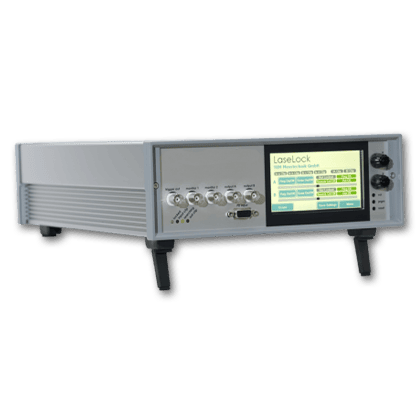
 Panel:
 From left to right:
Power Interface: 3.81mm connector, 5V 3A
Communication Interface: Serial communication, baud rate 115200bps, 8 data bits, 1 stop bit, no parity bit; 3.3V TTL level.
You can use a jumper to short the GND and RX pins, causing the system to begin driving the laser according to the preset internal current. Please make sure all parameters are properly set before using this function.
COM Light: Communication indicator light, which turns red when GND and RX are shorted.
SYS Light: System status light. It shows yellow when the laser is not installed or the laser temperature is not stable at the set value. It turns green when the laser temperature stabilizes. It turns red when the internal driving current is turned on.
INPUT: SMB connector, input voltage 02.5V, input frequency 0~10MHz.
External Signal Input
The signal input terminal INPUT on the rear panel of the instrument is used to receive external input. When the internal bias signal is not enabled, the equivalent circuit is as shown below:

The driving current of the laser is:
ILaser = (V1/1.25V) x Imax
Imax=149mA or 378mA
When the internal signal is turned on, the equivalent circuit is as follows:

If only the internal signal is used, all connections on the INPUT terminal should be disconnected. If both internal and external signals are to be used simultaneously, please calculate the final effect based on the equivalent circuit shown above.
PC Control Interface
Reassemble the instrument cover, connect the controller to the power supply, and connect the computer via a USB cable. Press the power button (①) to turn on the instrument. Windows 7 and above systems will automatically prompt for the USB driver installation. If using other systems or if automatic installation fails, please download the appropriate driver from http://www.ftdichip.com/Drivers/VCP.htm. Once the driver is installed, a virtual serial device will appear in the "Device Manager." Then, open the dedicated software on the computer, as shown below:
 In the Communication Port, find the corresponding virtual serial port. If not found, click the Refresh button. Click the Connect button, and after a successful handshake, the console will light up, and the current settings of the controller will be read. In the LD Temp Setpoint, enter the required working temperature and click Set Temperature to set it. Use the Start slider to set the constant operating current value, and the Limit slider to set the maximum current limit. Click the Set Parameters button to send the settings to the instrument. Click Save All Settings to save all parameters to the instrument.
Click Run:DC to start the laser at the set current value. The Limit slider is used to protect the laser and can also limit the current in the case of external input. Please set it to the maximum working current specified in the laser’s parameter table.
Before starting the laser, please carefully check that all parameters are within the laser's allowable operating range!
Communication Instructions
The dedicated conversion cable connects the circuit board to the computer's USB or serial port. The USB converter uses the FT232R chip to simulate a serial port. For systems with Windows 7 or above, the driver will be automatically installed via the internet. For other systems or when not connected to the internet, please download the corresponding driver from http://www.ftdichip.com/Drivers/VCP.htm. After the driver is installed, a new serial device will appear in the "Device Manager", and the communication rate is set to 115200bps by default.
To change parameters, ASCII format serial commands are used, and the commands end with a carriage return.
The following is an example of how to use PuTTY for communication. After opening PuTTY, select Serial for the connection type, input the port number corresponding to the one in the Device Manager, set Speed to 115200, and then click Open to open the black interactive port. You can then input relevant commands using the keyboard (the Backspace key does not work). After entering the correct command, the system will prompt the setting results. If there is an error, an error message will be returned.

The computer acts as the master (host), sending string commands. Each command starts with a colon (":") and ends with a carriage return (\r\n). After the lower machine executes the command, it returns the corresponding information. All the following functions can be accessed via the provided software. It is recommended to use the accompanying LDPD software to complete the settings and obtain the correct waveform. Afterward, click Save to save the parameters to the lower machine, and then other clients can take control.
The operating modes are as follows:
1 | Operating Modes |
>>>>>> send auto on to start,return(1)Auto run started.[[OK]]\r\n >>>>>> Laser current set as configured >>>>>> send auto off to stop, return(0)Auto run stopped.[[OK]]\r\n |
send | Function and Return Values |
about | Return the current parameters of the lower machine: >> First line (%f) TEC.\r\n >> (Floating point number, consistent with the issued parameter) >> Second line (%d, %d, %d) PGA, freq, amp.\r\n >> (For LDRV module, the above parameters are meaningless) >> Third line (%d, %d, %d) bias.\r\n >> ((Values consistent with the issued command bias a, b, c) >> Fourth line (%d, %d) dm, phase.\r\n >> (For LDRV, these parameters are meaningless) |
version | Reply: RYMLASER |
temp | Returns the current ambient temperature value and laser temperature. |
tec x | Sets the target temperature for the laser, where x is the temperature in Celsius, which can be a decimal. |
tecpkPkI kD | Sets the PID parameters for the temperature control system to ensure stability. The user can adjust the parameters to achieve faster or slower response. |
For professional users only! Incorrect PID parameters may cause temperature oscillation and even damage the laser. Factory default values:kP =1500; kI=4000; kD=10 | |
tecfast | TEC standard mode, using the stored PID parameters. |
tecslow | TEC slow mode, setting kP/2, kI/8, which will reduce the time constant of the temperature control system. |
bias abc | · a: Current setting (0~65535) · b: Current limit setting (0~65535) · c: Meaningless parameter, set to 1 or higher. |
save | Save all current parameters, which will be automatically called upon the next startup. |
Installation Precautions:
Insulation of Laser with Shell:
If the laser has functional pins connected to the shell (e.g., NEL laser, where the LD anode is typically connected to the shell), the laser shell must be insulated from the base. Place a layer of thermal silicone gel under the laser and avoid using metal screws to secure it.
Laser Current Setting:
The laser current setting is achieved through jumper caps and then identified by the system using switch 1. If there is a mismatch between the jumper cap and the switch setting, it will result in incorrect system self-recognition and may cause the laser to burn out!
Test Setup:
It is recommended to first connect an LED or a low-cost red laser to test if the current settings are working correctly.
Temperature Oscillation:
If there is temperature oscillation, the PID settings for the temperature controller are incorrect. All temperature controllers have PID parameter adjustment stages, and you can refer to various online guidelines for tuning. Temperature control parameter adjustment commands are tecp, kp, kl, and kd. Changes will take effect immediately, so observe the temperature response accuracy and speed. After adjustment, use the save command to store the settings.
No Power Switch:
The module does not have a power switch. Once the power is connected, the TEC part starts working immediately, but the laser current source does not start. A green light indicates that the temperature has stabilized. Use a jumper cap to short RX and GND to start the current source. Ensure that all parameters are fully set before using this function.
--
⇪