- Cart
- |
- Personal Center
- |
info@idealphotonics.com


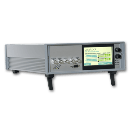
WG3010 Integral Sphere Power Meter
The WG3010 is an integrating sphere optical power meter, operating in the range of 700 to 1700 nm, with 21 calibration wavelengths. It uses an integrating sphere probe to measure optical power in the range of 1 μW to 20 W, and features a separated external probe structure and display main unit. The device is characterized by fast data acquisition speed, high measurement accuracy, and good repeatability. It is equipped with built-in USB and RS232 communication interfaces, allowing remote control through upper-level software to build an automated testing platform
Product features:External integrating sphere probe、 High measurement accuracy and fast refresh rate、 3.5-inch full-color LCD screen display interface、 Equipped with USB and RS232 communication interfaces
Part Number:--
Application area:
Add to Cart Consult Favorite
Parameters
Parameter | Unit | Specs |
Detector Type | InGaAs | |
Detector Diameter | mm | 2 |
Operating Wavelength | nm | 850/1270/1290/1310/1330/1350/1370/1390/1410/1430/1450/1470/ 1490/1510/1530/1550/1570/1590/1610/1625/1650 |
Measurement Range | 1uW~20W | |
Display Units | mW/dBm/dB | |
Measurement Accuracy | dB | 0.1 |
Linearity | dB | 0.1 |
Resolution | dB | 0.01 |
Communication Interface | USB/RS232 | |
Power Supply | V | AC 160~280 |
Operating Temperature | ℃ | -10~+50 |
![]()
Storage Temperature | ℃ | -20~+70 |
Storage Humidity | ≤90%RH | |
Dimensions | mm | 205´205´100 (L × W × H) |
Weight | kg | ≤1 |
Front Panel Definition
No. | Content | Description |
1 | 1490 nm | Displays the operating wavelength. |
2 | -70.00 | Displays the measured value. |
3 | dBm | Displays the unit of measurement. |
4 | Remote LED | LED indicator for remote control mode. |
5 | Button λ | Switches the operating wavelength. |
6 | Button Unit | Switches the display unit. |
7 | Button REF | Short press enters relative measurement mode. Long press for over 2 seconds to set the reference value and enter relative measurement mode. |
8 | Input Light Port | Input Light Port |
Rear Panel Definition

No. | Content | Description |
1 | RS232 | RS232 Communication Port |
2 | USB | USB Communication Port |
3 | POWER | System Power Switch |
4 | AC220V | AC220V Power Input |
![]()
USB/RS232 Communication Interface
The instrument can be programmed and controlled via either USB or RS232 interfaces. When the USB interface is connected to a PC, the RS232 interface is automatically disabled. After installing the USB driver on the PC, the USB port is converted into a COM port on the PC. Therefore, both the USB and RS232 ports share the same command set.
Serial port settings:Baud rate: 115200, Start bit: 1 bit, Data bits: 8 bits, Stop bit: 1 bi,t Parity: None.The communication mechanism of this device is a request-response model. Each time the host computer sends a command, the device will respond. The command from the host and the device's response are encapsulated in a data frame. The frame length is fixed at 16 bytes, and both start with 0xAA. The remaining bytes represent the type and parameters of the command or response. If the command frame does not start with 0xAA, the device will not respond.
The host computer should not send a new command until receiving the response from the device, as sending new commands before receiving a response may compromise the integrity of the previous command.
1、Read the current light power measurement value.


(*All two-digit numbers in the above table are in hexadecimal format, where "xx" represents any hexadecimal number. The same applies hereafter.)
As shown in the table above, after the host sends a command frame starting with "aa, 01, 02", it reads the current optical power values of the integrating sphere.
The optical power value and the detector optical power value are in dBm, where S1/OP1 is the integrating sphere optical power value and S2/OP2 is the detector optical power value. Byte 9 (S1) and Byte 12 (S2) indicate the sign of the optical power value, with 0 for positive and 1 for negative. The double-byte values OP1/OP2 represent the absolute optical power, where the highest 4 bits represent 10 dBm, the next 4 bits represent 1 dBm, the next 4 bits represent 0.1 dBm, and the lowest 4 bits represent 0.01 dBm.
Byte 5 (λ) in the response frame represents the current operating wavelength, with possible values from 0 to 20, corresponding to 850/1270/1290/1310/1330/1350/1370/1390/1410/1430/1450/1470/1490/1510/1530/1550/1570/1590/1610/1625/1650 nm. Byte 6 (U) represents the current display unit, with possible values from 0 to 2, corresponding to mW/dBm/dB (the optical power value is always in dBm regardless of U).
2、设Set Working Wavelength
Command Frame:

Response Frame:

This command sets the working wavelength of the optical power meter. The λ in the command frame represents the wavelength value to be set, with possible values ranging from 0 to 20, corresponding to the wavelengths: 850/1270/1290/1310/1330/1350/1370/1390/1410/1430/1450/1470/1490/1510/1530/1550/1570/1590/1610/1625/1650nm. The response frame is simply a copy of the command frame parameters, without carrying any other meaningful information.。
3、Set display unit
Command Frame:

Response Frame:

This command specifies the display unit of the optical power meter. In the command frame, U represents the display unit to be set, with possible values of 0~2, corresponding to mW/dBm/dB, respectively. The response frame simply copies the parameters from the command frame and does not carry any other meaningful information.
4、Set Reference Value
Command Frame:

Response Frame:

This command sets the current measurement value as the reference value. The response frame does not carry any other meaningful information.。
5、The command to turn the buzzer on/off during serial communication response process
Command Frame:

Response Frame:

This command turns the buzzer on or off during the serial command response process. By default, the buzzer sounds once for each serial command response when the device is powered on. This can be reconfigured using this command. When B=0, the buzzer is turned off; when B=1, the buzzer is turned on. Note that this command does not affect the buzzer sound during the key press response process。
6、This command enters or exits the program control mode
Command Frame:

Response Frame:

When R=1, the instrument enters program control mode, and the Remote LED light turns on. In program control mode, the instrument's keys are locked to prevent accidental key presses from changing the working state. When R=0, the instrument exits program control mode, and the Remote LED light turns off. The default state when powered on is non-program control mode.
7、The command reads the device model number
Command Frame:

Response Frame:

This command reads the device model word. Bytes 5 to 16 in the response frame store the 12 ASCII characters of the device model. This command can be used for testing serial communication during software debugging.
8、This command reads the device serial number
Command Frame:

Response Frame:

This command reads the device serial number. In the response frame, bytes 5 to 16 store the 12 ASCII characters of the device serial number. This command can be used for software debugging to test whether the serial communication is functioning properly。
Packaging and Standard Accessories
No. | Content | Quantity |
1 | Main unit | 1 |
2 | External probe module | |
3 | Power cable | 1 |
4 | USB data cable | 1 |
--
⇪