- Cart
- |
- Personal Center
- |
info@idealphotonics.com


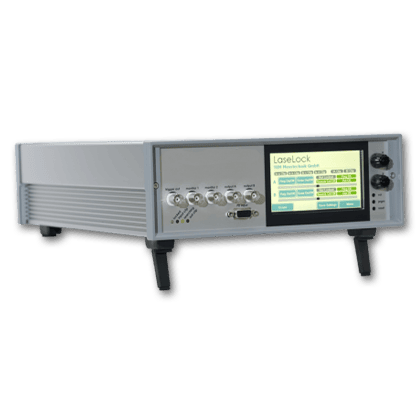
Ultra-low noise laser diode linear driver module
LDRVMLN is a current drive and temperature control module for butterfly semiconductor laser diodes. Its main functions include: controlling the internal temperature of the laser, generating a constant current signal to drive the laser, and converting the external input voltage signal into a current drive. The module has three Max. current drive ranges, suitable for lasers of different power sizes (selected by circuit board jumpers). The built-in reference source has an extremely low noise level and can achieve 16-bit control accuracy. Both current and temperature parameters can be stored on the module, and the laser can be run with these parameters via a simple external trigger signal. This makes the module a plug-and-play, ultra-high stability laser light source.
Product features:
Part Number:--
Application area:
Add to Cart Consult Favorite
Parameters
Parameter | Min. | Max. | Unit | Notes |
Supply voltage | 4.8 | 6.1 | VDC | DC It is recommended to use a regulated power supply |
Power | 10 | W | ||
Maximum drive current | 149/ 378/ 624 | mA | Jumper selection | |
Current resolution (LSB) | Maximum current /65536 | mA | ||
Current linearity | ±1 | LSB | ||
Current temperature drift | ±25 | ppm/℃ | ||
Current noise | 200 | pA/Hz1/2 | Only built-in reference source | |
Laser drive voltage Response frequency | 3.4/2.8 | V | 5V power supply Half amplitude current/full amplitude current | |
4.3/3.7 | V | 6V power supply Half amplitude current/full amplitude current | ||
Temperature control range | 0 | 25 | MHz | -3db |
Temperature resolution | -10 | 50 | oC | |
Temperature stability | 0.001 | oC | ||
TEC output current | 0.002 | oC | Housing heat dissipation required | |
TEC output voltage | -1.5 | 1.5 | A | |
Analog input | -4.6 | +4.6 | V | |
Supply voltage | 0 | 2.5 | V |
Installation
Please be sure to refer to the laser manual, the wiring sequence of the corresponding connector, and the connection on the circuit board to make sure that the laser is compatible with the current wiring sequence. Powering on with an incorrect wiring sequence may damage the laser!
The negative input of the power supply of the module, the bottom plate and the negative pole of the NTC are all grounded. And the positive and negative poles of the drive output are not grounded. When any function pin of the laser to be installed is grounded (connected to its shell), special attention should be paid.
When there is a grounding situation of the laser function pin (such as the positive pole of the laser is grounded), a piece of sticky thermal conductive silicone needs to be placed between the laser and the bottom shell, and do not use metal screws to fix the laser to insulate the laser shell from the bottom shell. If you are not sure, please consult the engineer of the seller. Improper grounding will cause abnormal function of the module or even burn the laser!
Line configuration
Before powering on, the module needs to adjust the circuit parameters to adapt to the installed laser. The parameters are controlled by the jumper and dip switch on the circuit board. Be sure to operate with power off!
Please set the Max. drive current of LDRVMLN to be equal to or slightly larger than the Max. allowable current of the laser. If the drive current is set too high, the risk of burning out the laser will increase. Set the jumpers P3 and P10 on the circuit board:
Current selection jumper status | Instrument model/maximum drive current |
 | LDRVMLN150 149mA |
 | LDRVMLN380 378mA |
 | LDRVMLN600 624mA |
 | LDRVMLN400 394mA |
The jumpers P3 and P10 must be consistent, otherwise the instrument will not work properly! All operations should be performed with the power off.
Voltage selection line | ||
Input current | 5V | Maximum drive operating voltage |
5V | Closed | 2.8V |
6V | Cut off | 3.7V |
If the laser has a built-in voltage divider resistor, try not to use it, as it will cause insufficient external drive voltage and the laser will be in an undervoltage state.
The green light indicates that the temperature has stabilized. Use a jumper cap to short RX and GND to start the current source. Please use this function after the parameters are fully set!
External signal input
The signal input terminal INPUT on the rear panel of the instrument is used to receive external input. When the internal bias signal is not turned on, the equivalent circuit is shown in the figure below:

The driving current of the laser is:
ILaser = (V1/1.25V) x Imax
Imax=149mA, 378mA etc
When the internal signal is turned on, the equivalent circuit is as follows:

If only internal signals are used, all connections on the INPUT interface should be disconnected. If internal and external signals are to be used simultaneously, please calculate the final effect yourself according to the equivalent circuit mentioned above.
PC control interface
Replace the instrument cover, connect the controller to the power supply, and connect it to the computer with a USB cable. WIN7 and above systems will prompt to automatically connect to the Internet to install the USB driver. When using other systems or unable to connect to the Internet
Please download the corresponding driver at http://www.ftdichip.com/Drivers/VCP.htm. After the driver is installed, a virtual serial device will appear in the "Device Manager".
Open the computer-side dedicated software, as shown below:

The computer is the main control end (host computer) and sends a string command. A line of command starts with a colon ":" and ends with a carriage return (\r\n). The lower computer returns information after execution. All the following functions can be accessed through the supporting software.
It is recommended to complete the settings with the supporting LDPD software and get the correct waveform, then click Save to save the parameters to the lower computer, and then transfer it to other clients for control.
The operation mode is as follows:
1 | Operation Mode |
>>>>>> Send auto on to start, return (1) Auto run started. [[OK]]\r\n >>>>>> The laser loads the set current >>>>>> Send auto off to stop, return (0) Auto run stopped. [[OK]]\r\n |
Parameter settings:
Send | Function and return value |
about | Return the current parameters of the lower computer: >> First line (%f) TEC.\r\n >> (floating point number, consistent with the parameters sent) |
>> The second line (%d,%d,%d) PGA,freq,amp.\r\n >> (For the LDRV module, the above parameters are meaningless) >> The third line (%d,%d,%d) bias.\r\n >> (The value is consistent with the bias a,b,c command) >> The fourth line (%d,%d) dm,phase.\r\n >> (The parameters are meaningless on LDRV) | |
version | Reply: RYMLASER |
temp | Returns the current ambient temperature, laser temperature, and read current value |
tec x | x is the Celsius temperature, which sets the target temperature of the laser and can be a decimal. |
tecp kP kI kD | Set the PID parameters of the temperature control system to ensure the stability of the temperature control system. Users can adjust the parameters to achieve fast or slow response. For professional users only! Poor PID parameters will cause temperature oscillation and even damage the laser. System factory values: kP = 1500; kI = 4000; kD = 10 |
tecfast | TEC normal mode, using stored PID parameters |
tecslow | TEC slow mode, kP/2, kI/8, will reduce the time constant of the temperature system |
bias a b c | a: Current setting (0~65535) b: Current limit setting (0~65535) c: Meaningless parameter, set to 1 or above. The values of a and b are calculated by the following formula a = (Iset/Imax)*65536 Iset is the current to be set, and Imax is the maximum current of the instrument (check in Instruments.ini according to the model of the machine) |
save | Save all current parameters and they will be automatically called next time the computer is turned on. |
--
⇪