- Cart
- |
- Personal Center
- |
info@idealphotonics.com


VCSEL Laser Driver 20mA Maximum Voltage 4V DB9 Output Interface
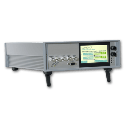
Idealphotonics' VCSEL laser driver features a full aluminum housing, offering excellent heat dissipation and shell strength to ensure stable and reliable long-term operation. It includes a 2.4-inch OLED display with large, clear fonts. The built-in low-noise adjustable constant current driver and TEC control are integrated. The VCSEL driver base, developed and designed by us, allows for easy insertion of the laser's pins, facilitating testing. It supports software-controlled operation and can also accept external modulation signals. Customization is available based on the laser's pin definitions.
Product features:Compact structure 、Easy operation 、Software control
Part Number:--
Application area:Gas analysis 、Laser driver
Add to Cart Consult Favorite
Parameter
Technical Specifications | Parameters |
Operating Voltage | 220VAC |
Power Frequency | 50Hz |
Power (Max) | 6W |
Maximum Laser Tube Drive Voltage | 4V |
Maximum Laser Control Temperature | 50.0℃ |
Minimum Laser Control Temperature | 5.0℃ |
TEC Drive Current (Low) | 0.13A |
TEC Drive Current (High) | 0.3A |
Laser Drive Current | 0-20mA |
Modulation Voltage | 0-15V |
Modulation Frequency | 300k |
Note: Output interface DB9
Software Interface

1550nm VCSEL Laser Experimental Test Case
1.Without External Modulation
 (1) Connect the 1550nm TOSA laser to an LC-APC connection cable, then insert the laser into the driver base and connect it to the driver. The other end of the connection cable is linked to a spectrometer or power meter.
(2) Connect the USB cable to the computer, open the driver software, set the maximum current to 20mA in the software, configure it to internal modulation (inter), click SET, and the setup is complete.
(3) Set the current and turn on the laser.
Test result


2.With External Modulation Using a Signal Generator
(1) Set the signal generator to sweep mode.
When a fixed frequency of 50KHz is set, the corresponding spectral diagrams for different voltages are as follows:

3V

6V

9V

12V
Laser Pin Definition Description


--
⇪