- Cart
- |
- Personal Center
- |

400-1100nm Four-quadrant Si photodetector (N-type silicon quadrant detector, photosensitive surface diameter 16mm, DC responsivity 0.3A/W)
The device is an N-type silicon quadrant detector. When the radiation flux of light radiating to each quadrant of the device is equal, the photocurrent output of each quadrant is equal. When the target is offset, the change of radiation flux between quadrants causes the change of output photocurrent of each quadrant, thereby measuring the direction of the object, thus playing the role of tracking and guiding.
Product features:Low dark current、 High uniformity and symmetry、 High reliability、 Small blind spot
Part Number:--
Application area:Laser aiming, guidance, tracking and exploration device、 Precision measurement system such as laser micro-positioning and displacement monitoring
Add to Cart Consult Favorite
Parameter
Parameter | Symbol | Test condition | Value | Unit | |||
(Unless otherwise specified, TA = 22°C ± 3°C) | Min. | Typical | Max. | ||||
Responsivity (AC) (quadrant) | Spi | λ=1.064μm | Pulse width 20 ns、Pin=2 mW | 0.25 | - | - | A/W |
Responsivity (DC) (quadrant) | Rei | DC、Pin=1μw | 0.3 | - | - | ||
Responsivity (AC) (quadrant)a | ΔRei | VR=135 V | TA=-45 ℃±2 ℃ | - | - | 50 | % |
Responsivity (DC) (quadrant)a | |||||||
Dark current (quadrant) | IDi | VR=135V | TA=22℃±3℃ | - | - | 1 | μA |
TA=70℃±3℃ | - | - | 10 | ||||
Dark current (ring) | ID | Pin=0μw | TA=22℃±3℃ | - | - | 10 | |
TA=70℃±3℃ | - | - | 100 | ||||
Junction capacitance (quadrant) | Cji | VR=135V,f=1MHz | - | - | 15 | pF | |
Active area | φ | 10 | - | 16 | mm | ||
Equivalent noise power | NEPi | λ=1.064 μm,VR=135 V ,pulse width 20 ns | - | - | 5×10-12 | W/HZ1/2 | |
Breakdown voltage (quadrant, ring) | V BR | IR=10μA | 200 | - | - | V | |
Inter-pixel sensitivity non-uniformity | Rf | λ=1.064 μm,VR=135 V, pulse width 20 ns;Pin=2mW | - | - | 5 | % | |
Intra-pixel sensitivity non-uniformity | Rf n | λ=1.064 μm,VR=135 V, pulse width 20 ns;Pin=2mW | - | - | 5 | % | |
Inter-pixel crosstalk factor | SLi | λ=1.064 μm,VR=135 V, pulse width 20 ns;Pin=2mW | - | - | 5 | % | |
element gap | - | - | - | 0.2 | - | mm | |
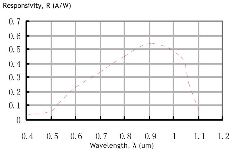
Spectrum responsivity curve

Appearance and structure
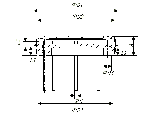
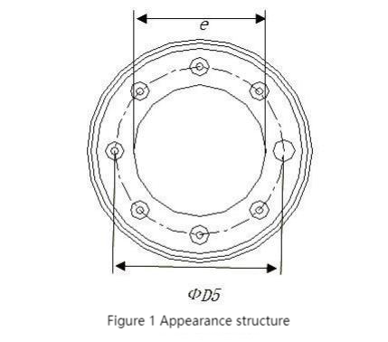
TO type airtight package. The appearance and structure are shown in Figure 1, and the dimensions are shown in Table 1.


Table 1 appearance dimension (unit mm)
Dimension symbol | φ D1 | Φ D2 | Φ D3 | Φ D4 | Φ D5 | Φ d | A | L1 | L2 | L3 | e |
Min. | 30. 55 | 27. 80 | 3. 00 | 27. 915 | 22. 60 | 0. 98 | 7. 03 | 3. 02 | 1. 85 | 2. 70 | 18. 00 |
Max. | 30. 65 | 28. 00 | 3. 06 | 27. 94 | 23. 40 | 1. 02 | 7. 20 | 3. 10 | 1. 95 | 3. 00 | 18. 05 |
Pin arrangement
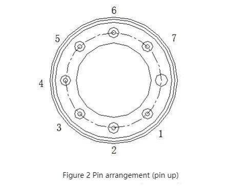
The pin arrangement of the device is shown in Figure 2. The pin functions should comply with the requirements of Table 2.

Table 2 Pin Function Table
Pin | Function | Voltage polarity |
1 | Quadrant 1 | Positive |
2 | Public P level | Negative |
3 | Quadrant 4 | Positive |
4 | Ring level | Positive |
5 | Quadrant 3 | Positive |
6 | Case | Ground |
7 | Quadrant 2 | Positive |
--
⇪