- Cart
- |
- Personal Center
- |

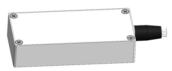

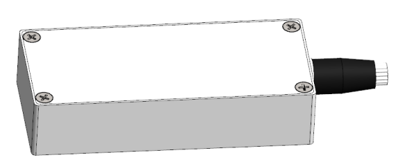

MEMS Optical Switch Module
This model of optical switch module (hereinafter referred to as MEMS optical switch) is a module product with multi-channel optical path switching function. The MEMS optical switch product is an optical switch manufactured using the electrostatically driven micro-mirror scheme, featuring small size, fast response speed and stable performance, and can be widely used in various optical communication and testing systems.
Product features:
Part Number:--
Application area:
Add to Cart Consult Favorite

Optical Schematic Diagram
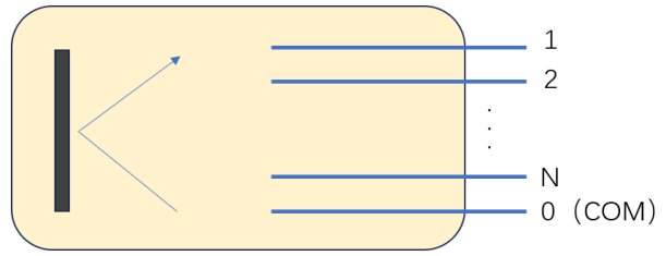
Figuer1. Optical Schematic Diagram
Performance Parameters
Parameters | Unit | SM | MM | ||||||||||||
Number of Channels | CH | 2 | 4 | 8 | 12 | 16 | 24 | 36 | 48 | 64 | 2 | 4 | 8 | 12 | 16 |
Wavelength Range | nm | 1260-1650 | 850 ±30 / 1310 ±30 | ||||||||||||
Test Wavelength | nm | 1310 or 1550 | 850 or 1310 | ||||||||||||
Loss (Max) | dB | 0.6 | 0.8 | 1.2 | 1.2 | 1.2 | 1.6 | 2.0 | 2.5 | 2.8 | 0.6 | 0.8 | 1.2 | 1.2 | 1.2 |
Temperature-Dependent Loss | dB | ≤0.3 | |||||||||||||
Polarization-Dependent Loss | dB | ≤0.2 | |||||||||||||
Return Loss | dB | ≥50 | ≥30 | ||||||||||||
Crosstalk | dB | ≥45 | ≥30 | ||||||||||||
Repeatability | dB | ≤0.05 | |||||||||||||
Switching Time | ms | ≤15 | |||||||||||||
Service Life | Cycle | ≥109 | |||||||||||||
Input Optical Power | mW | ≤500 | |||||||||||||
Drive Voltage | V | 5 | |||||||||||||
Power Consumption | mW | ≤350 | |||||||||||||
Operating Temperature | ℃ | -5~70 | |||||||||||||
Storage Temperature | ℃ | -40~85 | |||||||||||||
Dimensions | mm | 68x30x14±0.2 | |||||||||||||
Working Mode | TTL/UART | ||||||||||||||
Note: 1 Test at room temperature and SOP. 2 Excluding connectors, 0.2dB for one pair connectors. 3 IL is for single-band, Dual-band adds 0.3dB | |||||||||||||||
Electrical Characteristics
Serial Number | Parameter | Unit | Min | Typ | Max |
1 | Supply Voltage | V | 3 | / | 13 |
2 | Digital I/O Logic High Level | V | 2.0 | 3.3 | 3.6 |
3 | Digital I/O Logic Low Level | V | 0 | 0.5 | 0.8 |
Mechanical Dimensions (Unit: mm)
4 ≤ N ≤ 16 (0.9mm fiber optic protective sleeve):
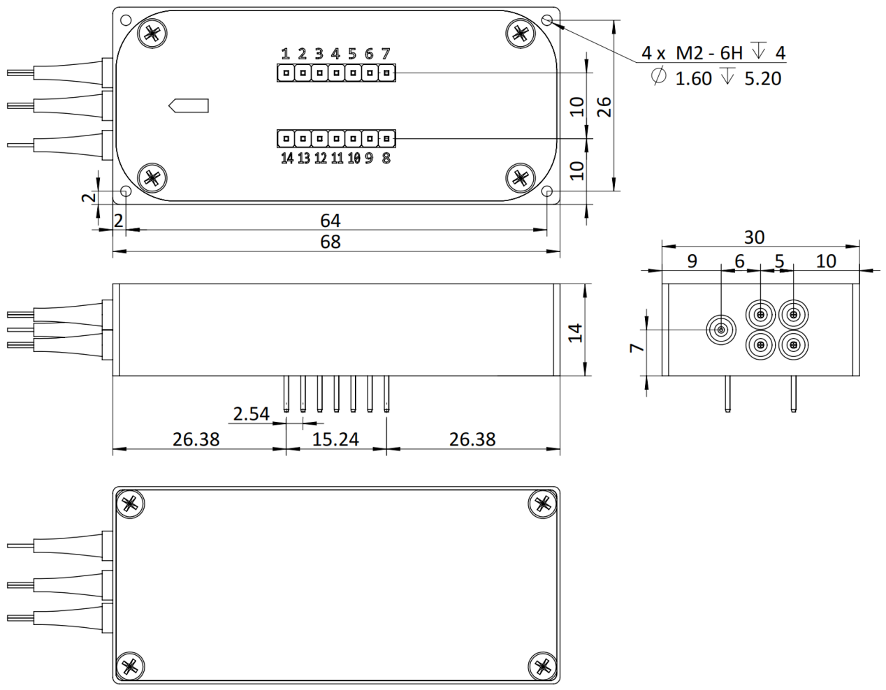
Figure 2 Mechanical Dimensions Drawing (4 ≤ N ≤ 16)
16 < N ≤ 24 (0.9mm fiber optic protective sleeve) or N ≤ 64 (bare fiber):
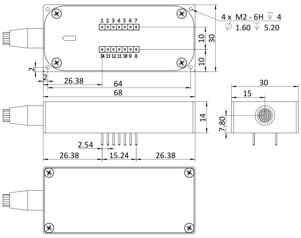
Figure 3. Mechanical Dimensions Drawing (16 ≤ N ≤ 24)
24 < N ≤ 48 (0.9mm fiber optic protective sleeve):
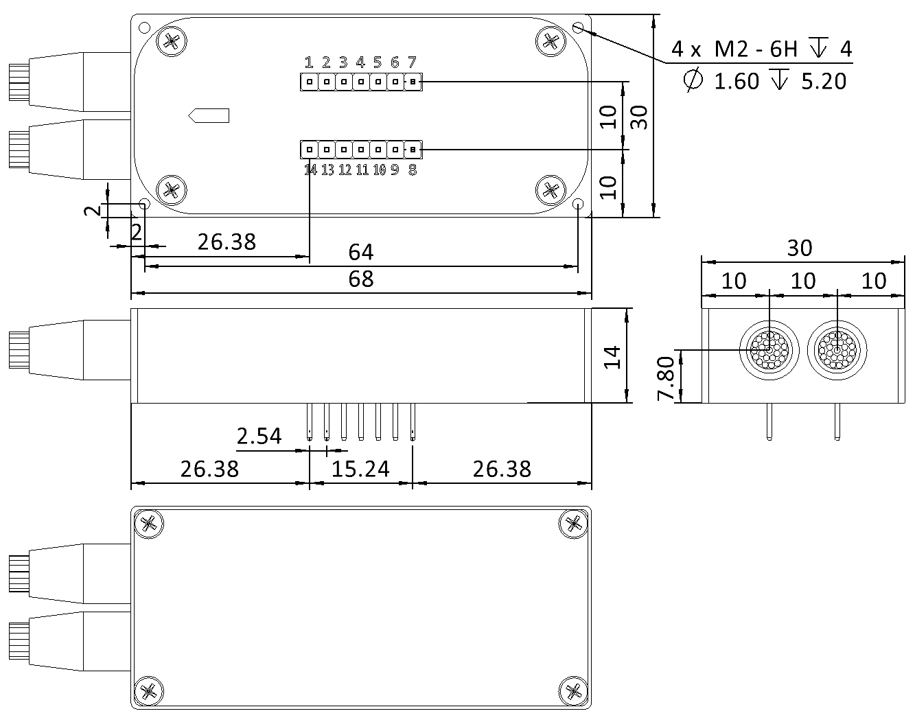
Figure 4. Mechanical Dimensions Drawing (24 < N ≤ 48)
Pin Definition
Pin Number | Pin Definition | Pin Type | Level Standard | Function Description |
1 | VCC | Power IN | / | DC 5V, positive power input |
2 | /RESET | IN | LVTTL | Reset, active low, pulse width ≥ 0.5ms |
3 | /STROBE1 | IN | LVTTL | TTL strobe: active on falling edge |
4 | RX | IN | LVTTL | Serial port receive |
5 | TX | OUT | LVTTL | Serial port transmit |
6 | GND | / | / | Signal ground |
7 | AGND | Power IN | / | Power ground/analog ground |
8 | NC | / | / | Forbidden electrical connection |
9 | D02 | IN | LVTTL | TTL input: data bit D0 input |
10 | D12 | IN | LVTTL | TTL input: data bit D1 input |
11 | D22 | IN | LVTTL | TTL input: data bit D2 input |
12 | D32 | IN | LVTTL | TTL input: data bit D3 input |
13 | D42 | IN | LVTTL | TTL input: data bit D4 input |
14 | D52 | IN | LVTTL | TTL input: data bit D5 input |
1.LVTTL strobe signal/STROBE: Defaults to high level; the falling edge triggers the parallel input data of LVTTL inputs D0~D5. 2.LVTTL input signals/D0-D5: Default to low level; the corresponding relationship between pins and channels is detailed in Table 4. | ||||
Data Bit Switching Logic Table
Channel1 | D5 | D4 | D3 | D2 | D1 | D0 |
COM1 | 0 | 0 | 0 | 0 | 0 | 0 |
COM2 | 0 | 0 | 0 | 0 | 0 | 1 |
COM3 | 0 | 0 | 0 | 0 | 1 | 0 |
COM4 | 0 | 0 | 0 | 0 | 1 | 1 |
COM5 | 0 | 0 | 0 | 1 | 0 | 0 |
COM6 | 0 | 0 | 0 | 1 | 0 | 1 |
COM7 | 0 | 0 | 0 | 1 | 1 | 0 |
COM8 | 0 | 0 | 0 | 1 | 1 | 1 |
COM9 | 0 | 0 | 1 | 0 | 0 | 0 |
COM10 | 0 | 0 | 1 | 0 | 0 | 1 |
... | ... | ... | ... | ... | ... | ... |
COM64 | 1 | 1 | 1 | 1 | 1 | 1 |
During use, the TTL control pins should be configured according to the actual number of optical paths. | ||||||
Description of Communication Methods
Communication Mode | UART |
Baud Rate | 115200bps, 8 data bits, 1 stop bit, no parity bit. |
Command Encoding Format | ASCII |
Overview of User Communication Command Set
Command 1 | Function Description | Return Information after Success 2 | Remark Description |
Switch to channel x | x is the channel number (0 ≤ x ≤ chnNum4) | ||
Query current channel | x is the channel number (0 ≤ x ≤ chnNum4) | ||
Query number of channels | x is the number of module channels (0 ≤ x ≤ chnNum4) | ||
Query module SN | "a…z" is the module SN number | ||
Query module PN | "a…z" is the module PN number | ||
1.All communication commands contain no space symbols, and all symbols are English symbols; please use uppercase letters. 2.For more "return information" and operation examples, see Tables 8 to 10. 3.Both the "CHN:x" command and LVTTL parallel port triggering can independently control channel switching. When x is 0, the module optical path resets. 4."chnNum" is the maximum number of channels of the optical switch module. | |||
Operation Instructions
LVTTL Parallel Digital I/O Control
The corresponding relationship between the level of LVTTL control pins and channels is shown in Table 4. During use, the LVTTL control pins should be configured according to the actual number of optical paths of the optical switch.
Time Characteristics:
Parameter | Minimum Value | Unit | Description |
T1 | 1 | ms | Minimum / GATE high time |
T2 | 15 | ms | Optical path switching time |
T3 | 100 | us | TTL_DATA setup time |
T4 | 2 | ms | TTL_DATA hold time |
Table 7. LVTTL Control Time Characteristics
The logic control diagram is as follows:

Figure 5. TTL Control Timing Diagram
1. Serial Port Control
1.1. For the definition of each pin of the module, see Table 3.
1.2. Connect the power cord. After power-on, the module is in a reset state with no output.
1.3. Control method:
1.3.1. Connect the serial communication line:
1.3.2. Serial port settings: 115200 baud rate, 8 data bits, 1 stop bit, no parity.
1.3.3. Input module commands as needed, and the commands will return information.
Detailed Explanation of Command Set
1.Detailed Explanation of User Communication
Command Set Switching and Querying Channel Commands
Command | Return Information | Explanation |
| The module has been switched to channel x. (0 < x ≤ chnNum) | |
Information returned when x is 0: the module stops outputting. | ||
The optical switch module initialization is not ready. | ||
The input channel number exceeds the range of the number of channels. | ||
The command is incorrect. | ||
| The module returns the number of the current working channel. | |
The module has no output. | ||
The command is incorrect. | ||
Note: 1. chnNumis the maximum number of channels of the mod | ||
Eg: 1.The user enters "CHN:15" in the serial port assistant, the module switches to COM15 channel, and the serial port assistant returns "CHN:15". 2.The user enters "
| ||
Command for querying the number of channels:
Command | Return Information | Description |
The module returns the number of channels, where x is the number of channels. | ||
The command is incorrect. | ||
Eg: 1. Assuming it is a 1x16 module, when the user enters " | ||
Query the SN number of the module:
Command | Return Information | Description |
"a…z" is the SN number of the module. | ||
The command is incorrect. | ||
Eg: 1.Assuming the SN number of the module is "2024111", when the user enters " | ||
Query the PN number of the module:
Command | Return Information | Description |
"a…z" is the PN number of the module. | ||
The command is incorrect. | ||
Eg: 1.Assuming the PN number of the module is "2024111", when the user enters " | ||
Ordering info
YFMS-A-B-C-D-E-F
A | B | C | D | E | F |
Channel | Fiber Type | Test Wavelength | Tube Type | Fiber Length | Connector |
1x4:1x4 1x8:1x8 1x12:1x12 1x16:1x16 1x24:1x24 1x36:1x36 1x48:1x48 1x64:1x64 | SM:G657A2 M5:MM ,50/125 M6:MM ,62.5/125 X:Others | 850:850nm 1310:1310nm 1550:1550nm 1315:1310nm&1550nm X:Others | 250: 250um 900: 900um X: Others | 05:0.5±5cm 10:1.0m±5cm X:Others | OO:None FC:FC/PC FA:FC/APC SC:SC/PC SA:SC/APC LC:LC/PC LA:LC/APC X:Others |
无
⇪